
 Chinese
 English
 français
 Deutsch
 italiano
 português
 Nederlands
 日本語
日本語 한국의
한국의




Categorías
Productos calientes
Patente CN215451487U - Selladora de laboratorio con matriz de cambio rápido
Sep 22,2026Una prensa selladora compacta, apta para cajas de guantes, para muestras de baterías de I+D: la matriz superior se intercambia mediante una espiga roscada y un pasador, y el soporte de la matriz inferior se desliza hacia afuera para su limpieza.
Especificaciones completas y dibujos: CN215451487U en Google Patents
Fabricar una muestra de investigación no es el mismo trabajo que fabricar una celda de producción. Una máquina selladora de baterías de laboratorio trabaja con pequeños lotes de materiales experimentales (a menudo dentro de una caja de guantes) y tiene que adaptarse cada vez que cambia la muestra. La especificación describe el estado de la técnica con franqueza: los dispositivos de sellado en las selladoras de laboratorio eran muchos y variados, y sellar un tipo diferente de batería significaba desmontar y volver a instalar la ranura de sellado de la matriz correspondiente, una operación que califica de inconveniente y problemática.
CN215451487U elimina esa tarea. La matriz de sellado superior se sujeta mediante una espiga roscada bloqueada con un pasador, por lo que puede desenroscarse e intercambiarse en momentos; el soporte de la matriz inferior se desplaza sobre una placa deslizante y se extrae a lo largo de rieles para su instalación y limpieza; y un dispositivo de soporte protege la placa deslizante cuando la prensa trabaja a alta fuerza.
Información de la patente
| Número de publicación | CN215451487U |
| Número de solicitud | CN202122023872.8U |
| Título (original) | 一种可自由更换封口装置的电池封口机 (Máquina selladora de baterías de laboratorio con matriz de cambio rápido) |
| Inventores | Huang Zhengyao (Dany Huang); Chen Lucai (Tobey Chen) |
| Cesionario actual | XIAMEN TOB NEW ENERGY TECHNOLOGY Co., Ltd. - la entidad registrada de TOB NEW ENERGY |
| Fecha de presentación | 26 de agosto de 2021 |
| Fecha de concesión | 7 de enero de 2022 |
| Tipo de documento | Modelo de utilidad (código de tipo U) |
| Estatus legal | Activo |
| Vencimiento previsto | 26 de agosto de 2031 |
| Dibujos | 5 figuras |
| Registro oficial | CN215451487U en Google Patents |
El problema de producción que resuelve esta patente
Cada tipo de muestra requiere su propio troquel.Se utiliza una selladora de laboratorio para fabricar muestras de investigación y desarrollo de materiales de batería. Los diferentes tipos de baterías necesitan diferentes ranuras de sellado de troquel, por lo que una máquina que no puede cambiar los troqueles rápidamente pasa la mayor parte de su tiempo siendo reequipada en lugar de sellar.
El cambio y la limpieza son complicados.La ranura del troquel debe ser desmontada y reinstalada a mano, y un troquel de sellado que no se puede extraer de la máquina es difícil de limpiar adecuadamente entre usos.
Las prensas de laboratorio deben soportar fuerzas de prensado reales.El sellado de muestras todavía requiere fuerza, y la especificación advierte que una presión excesiva puede dañar una placa deslizante o incluso agrietarla. La patente responde a los tres puntos: cambio rápido de troquel, una estación de troquel inferior extraíble y un dispositivo de soporte que absorbe la carga.
Cómo funciona el mecanismo
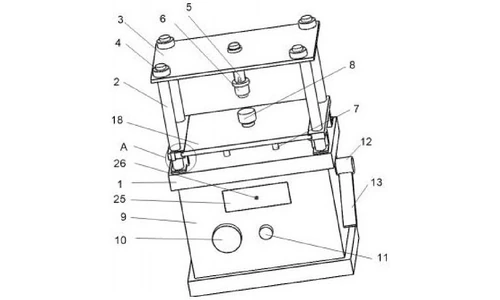
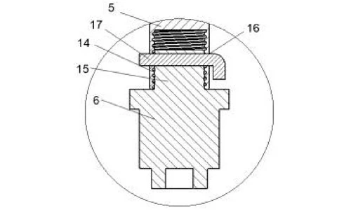
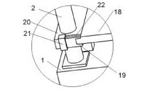
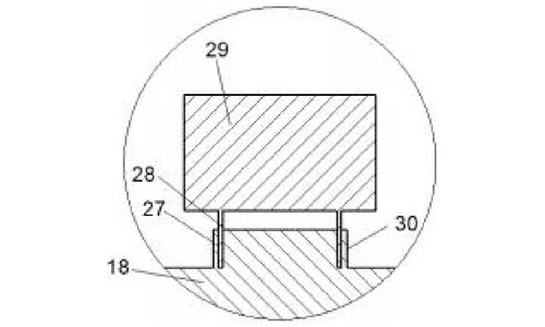
La máquina está construida como una pequeña prensa sobre una base, con la estación de troquel en una corredera frente al ariete y los controles de presión en el cuerpo inferior. La Figura 1 muestra la estructura general; la Figura 2 amplía la parte A del área de prensa; la Figura 3 muestra el dispositivo de soporte; las Figuras 4 y 5 muestran cómo se montan los troqueles superior e inferior.
Bastidor de prensa y ariete
Una columna de soporte está fijada sobre la base de la máquina, y una mesa de trabajo de estampado está conectada de forma móvil sobre la columna mediante un perno. Una columna de estampado cuelga de la parte inferior de la mesa de trabajo y lleva el troquel de sellado superior. Debajo de la base se encuentra el cuerpo de la máquina: su cara frontal lleva el manómetro y la válvula reguladora de presión, y su lado derecho lleva el asiento del interruptor de prensa con la palanca de prensa. Un cajón con asa está instalado en el cuerpo para almacenar los troqueles de sellado.
Troquel de sellado superior de cambio rápido
El extremo inferior de la columna de estampado tiene un orificio cilíndrico con una rosca interna. El troquel de sellado superior lleva un protuberancia cilíndrica con una rosca externa en su parte superior. La matriz se enrosca en la columna y ambas piezas tienen orificios redondos alineados orificios redondos a través de los cuales se inserta un pasador cilíndrico . El pasador bloquea la unión roscada para evitar que se afloje o gire durante el prensado. Para cambiar la matriz, el operador retira el pasador y desenrosca la matriz; la especificación indica que esto es lo que hace que la matriz de sellado superior sea reemplazable y fácil de desmontar.
Estación de matriz inferior extraíble
Sobre la base de la máquina se asienta el dispositivo de soporte; encima de él se desplaza una placa deslizante montada sobre rieles, y los rieles son transportados por un marco de soporte que pasa a través de la columna de soporte y comparte parte de la carga de prensado. El dispositivo de fijación de la matriz inferior - una protuberancia circular con una ranura anular que recibe el cilindro hueco en la parte inferior de la matriz de sellado inferior - está montado en la placa deslizante. Un perno de bloque deslizante en el marco de soporte se desplaza en una pequeña ranura para limitar y ubicar la placa deslizante. Debido a que todo el soporte de la matriz inferior se asienta sobre una corredera, se puede extraer a lo largo de la placa para la instalación y limpieza de la matriz.
Dispositivo de soporte debajo de la corredera
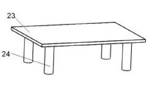
El dispositivo de soporte está hecho de una placa de soporte y cuatro columnas de soporte cuyos extremos inferiores están incrustados en la base de la máquina. Junto con el marco de soporte que pasa a través de la columna de soporte, absorbe parte de la fuerza de prensado. La especificación atribuye a esta disposición la prevención de daños o grietas en la placa deslizante bajo una presión excesiva.
Secuencia de operación según lo publicado
El experimentador observa el manómetro y ajusta la válvula reguladora a la presión prescrita por el experimento. El cilindro hueco de la matriz de sellado inferior se asienta en la ranura anular de la protuberancia circular en la placa deslizante, y la matriz de sellado superior se enrosca en la columna de estampado y se bloquea con el pasador cilíndrico. El material de la batería que se va a sellar se coloca en la matriz inferior, y al presionar la palanca de prensado se completa el sellado.
Beneficios declarados
| Beneficio | Mecanismo responsable |
|---|---|
| Matriz superior intercambiable y fácil de desmontar | Espiga cilíndrica roscada más bloqueo con pasador cilíndrico |
| Instalación y limpieza de la matriz convenientes | La placa deslizante y los rieles permiten extraer el dispositivo de fijación de la matriz inferior |
| Placa deslizante protegida contra presión excesiva | Dispositivo de soporte (placa de soporte con cuatro columnas de soporte integradas) y marco de soporte de distribución de carga |
| Fuerza de prensado controlada y repetible | Manómetro y válvula reguladora de presión en el cuerpo de la máquina |
Cómo se compara con las selladoras de laboratorio de matriz fija
Los diferentes tipos de muestras de baterías necesitan diferentes matrices de sellado. Una selladora cuya matriz no se puede cambiar rápidamente pasa la mayor parte de su tiempo siendo reequipada en lugar de sellar, el problema exacto que esta patente elimina.
| Dimensión | Enfoque convencional | Diseño de esta patente |
|---|---|---|
| Cambio de matriz superior | Reequipamiento lento entre tipos de muestra | La espiga roscada y el pasador cambian la matriz superior rápidamente |
| Acceso a la matriz inferior | Difícil de alcanzar para la limpieza | La placa deslizante y los rieles extraen la estación de la matriz inferior |
| Control de prensa | Fuerza ajustada manualmente inconsistente | Manómetro y válvula reguladora con soporte de distribución de carga debajo de la corredera |
Dónde se utiliza esta tecnología hoy en día
Esta patente cubre la arquitectura de matriz de cambio rápido del equipo de sellado de baterías de laboratorio de TOB, la misma familia de estaciones de trabajo utilizada para engarzar y sellar celdas de moneda de investigación y celdas de muestra con matrices que se intercambian en segundos.
- Máquinas de sellado / engarzado de baterías de laboratorio
- Equipo de laboratorio para cajas de guantes y salas secas
Consultas sobre equipos relacionados: solicitar un presupuesto
Preguntas frecuentes
¿Qué cubre la patente CN215451487U?
Cubre una máquina de sellado de baterías de laboratorio utilizada para fabricar muestras de I+D de materiales de batería, compacta para el funcionamiento en cajas de guantes y con una estructura de prensa hidráulica especial. Sus características clave son una matriz de sellado superior que se puede reemplazar rápidamente, un dispositivo de fijación de matriz inferior montado en una placa deslizante que se puede extraer para la instalación y limpieza de la matriz, y un dispositivo de soporte que evita daños por presión a la placa deslizante.
¿Por qué es importante una matriz de cambio rápido en una selladora de laboratorio?
Los diferentes tipos de baterías necesitan diferentes ranuras de sellado de matriz. En las selladoras de laboratorio anteriores, la ranura correspondiente tenía que ser desmontada y reinstalada para cada tipo de batería, lo cual la especificación describe como inconveniente y problemático. El utillaje de cambio rápido permite al operador cambiar las matrices y volver a sellar muestras.
¿Cómo se fija la matriz de sellado superior para que pueda cambiarse rápidamente?
La columna de estampado tiene un orificio cilíndrico con una rosca interna en su extremo inferior, y la matriz de sellado superior tiene una protuberancia cilíndrica con una rosca externa en la parte superior. La matriz se atornilla en la columna y se inserta un pasador cilíndrico a través de orificios redondos alineados en ambas partes, bloqueando la unión. Liberar el pasador y desenroscar la matriz completa el cambio.
¿Cómo se limpia o reemplaza la matriz de sellado inferior?
El dispositivo de fijación de la matriz inferior está montado en una placa deslizante que corre sobre rieles sobre el dispositivo de soporte. Todo el soporte se puede extraer a lo largo de la placa deslizante, lo que hace que la instalación y limpieza de la matriz sean convenientes sin desmontar la prensa.
¿Quién posee la patente CN215451487U?
TOB NEW ENERGY posee este modelo de utilidad concedido. Está registrado bajo su entidad china registrada y fue co-inventado por Huang Zhengyao (Dany Huang) y Chen Lucai (Tobey Chen).
¿Sigue vigente la patente CN215451487U?
Sí. Está activa, presentada el 26 de agosto de 2021 con vencimiento previsto para el 26 de agosto de 2031.
Especificación completa y dibujos: CN215451487U en Google Patents
 suscribete a nosotros



