Chinese
 English
 français
 Deutsch
 italiano
 português
 Nederlands
 日本語
 한국의




Categorías
Productos calientes
Patent CN215543717U - Dust & Iron Removal Unit for Calenders
Oct 19,2026C-shaped debris boxes with electromagnets, twin air pumps and screw-driven brush plates that keep calender rolls free of iron chips and dust without stopping the line - the cleaning patent behind TOB calendering equipment.
Full specification and drawings: CN215543717U on Google Patents
In electrode sheet production the calender (roller press) is where coating is densified onto the foil. The process must stay clean to keep the web defect-free - yet the specification of CN215543717U records a familiar production-floor problem: the roller presses then in use were very inconvenient to clean, and the machine had to be stopped for cleaning, which heavily cut production efficiency. Metal chips and coating dust also settle where they can be pressed back into the electrode.
CN215543717U, filed on 26 August 2021 and granted on 18 January 2022, answers with a self-cleaning unit built around the calender rolls: electromagnets pull ferrous chips out of the web zone, air pumps draw dust off the roll faces, and screw-driven brush plates sweep the captured debris into a collection drawer - all while the rolls keep turning.
Patent Information
| Publication number | CN215543717U |
| Application number | CN202122023666.7U |
| Title (original) | 一种锂电池辊压机极片除尘除铁装置 (Electrode Dust & Iron Removal Unit for Calenders) |
| Inventors | Huang Zhengyao (Dany Huang); Chen Lucai (Tobey Chen) |
| Current assignee | XIAMEN TOB NEW ENERGY TECHNOLOGY Co., Ltd. - the registered entity of TOB NEW ENERGY |
| Filing date | 26 August 2021 |
| Grant date | 18 January 2022 |
| Document type | Utility model (kind code U) |
| Legal status | Active |
| Anticipated expiration | 26 August 2031 |
| Drawings | 4 figures |
| Official record | Google Patents - CN215543717U |
The Production Problem This Patent Solves
Cleaning a calender used to mean stopping it. In the lithium battery electrode sheet process - mixing, coating, rolling, slitting, tab welding and more - rolling makes the active material bond to the foil densely and uniformly. But as rolls turn, dust and metal fragments accumulate on their faces, and the presses in use at the time had no way to be cleaned without halting the machine. The specification identifies that stoppage as a direct hit on production efficiency.
Iron is a different problem from dust. Ferrous particles near a calender are not just cosmetic dirt. If a metal chip is picked up by the web and pressed into the finished electrode it becomes a potential internal short circuit in the assembled cell. Suction alone cannot reliably lift magnetic chips off a moving roll - that is why the unit combines air suction with electromagnets.
Consistent rolling thickness also needs a stable process. The specification notes that different electrode tensions change the plasticity of the electrode material and directly influence the rolled thickness, so the machine that handles the web must not disturb tension while it cleans.
How the Mechanism Works
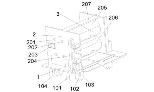
Frame and roll carriage (claim 1)
The unit is built on a bottom plate structure and two side plate structures that carry the upper and lower calender rolls. Each roll runs on a roll shaft mounted in the side plates, driven by motors on a motor frame that holds four motors. A control panel on the side structure is electrically connected to the four motors, the air pumps, both brush-plate motors, the electromagnets and the external power supply, so an operator starts and stops the whole cleaning cycle from one place.
Magnetic capture and vacuum pick-up (claim 1)
Beside each roll sits a debris attraction box whose cavity facing the roll is arc-shaped, so the whole box forms a C shape that hugs the roll. An electromagnet at the outer end of each box is energised during operation and attracts ferrous (iron) chips out of the roll zone. On the opposite side of each roll, suction ports connected by tubes to two air pumps draw dust and fine debris off the roll faces.
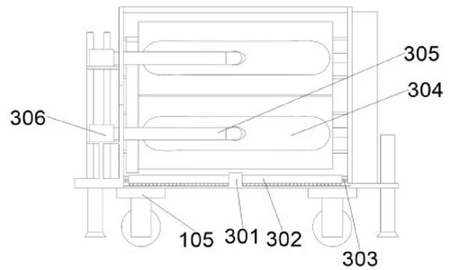
Screw-driven sweeping inside the debris boxes (claims 2 and 4)
Inside each debris attraction box, a square brush plate lined with fine bristles is threaded on a first lead screw mounted in the side plate structure. When the screw turns, the plate sweeps the chips that the electromagnet has pulled out of the web zone towards the collection end of the box.
Base-plate sweeping and collection drawer (claims 2 and 8)
A long brush plate motor in the middle of the bottom plate structure turns a second lead screw, and a long brush plate threaded on that screw carries bristles on its lower edge and both sides. It sweeps chips and dust that fall onto the bottom plate out of the machine. At the end of each debris box a debris collection box receives the swept debris; a drawer at its lower end, fitted with a handle, is pulled out for emptying.
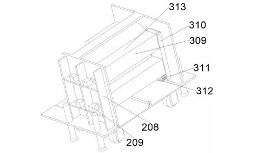
Mobility and anchoring (claims 5 to 7)
The bottom plate stands on four threaded levelling posts tipped with suction cups, so the unit is fixed firmly in front of the calender; a universal caster (roller wheel on a rotating disc) lets it be moved to the next machine when needed. A reinforcing plate between the two side plates stiffens the frame.
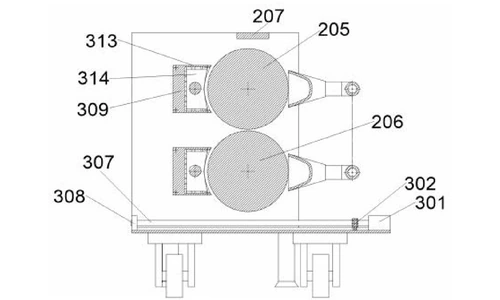
Working cycle
With the unit switched on through the control panel, the motors drive the upper and lower rolls, the electromagnets pull metal debris into the attraction boxes, and the air pumps draw dust from the roll faces. Periodically the control panel runs the two lead-screw motors: the square brush plates push the captured debris inside the boxes into the debris collection boxes, and the long brush plate sweeps the bottom plate clean.
Claimed Benefits
| Benefit | Mechanism responsible |
|---|---|
| Roll surfaces cleaned while the calender keeps running | Electromagnets plus twin air pumps acting on the moving upper and lower rolls |
| Ferrous chips removed even though suction alone could not lift them | Energised electromagnets in the C-shaped debris attraction boxes |
| Self-emptying capture path, no manual scraping of the rolls | Lead-screw-driven square and long brush plates sweeping into a drawer-equipped debris collection box |
| One-operator start and stop of the full cleaning cycle | Central control panel wired to motors, pumps, brush motors and electromagnets |
| Quick positioning at any calender and firm anchoring in use | Universal caster plus four suction-cup levelling posts; reinforcing plate between side plates |
How It Compares with Stopping the Calender to Clean It
Cleaning a calender used to mean stopping it. As the rolls turn, dust and metal fragments accumulate on the roll faces, and the presses in use had no way to remove them in production. This unit cleans while the calender keeps running.
| Dimension | Conventional approach | This patent design |
|---|---|---|
| Cleaning mode | Line stopped, rolls cleaned by hand | Electromagnets and twin air pumps clean the moving upper and lower rolls |
| Ferrous chips | Suction alone cannot lift heavy chips | Energised electromagnets in C-shaped debris boxes attract ferrous fragments |
| Residue path | Manual scraping of roll faces | Lead-screw-driven brush plates sweep debris into a drawer-equipped collector, started from one control panel |
Where This Technology Is Used Today
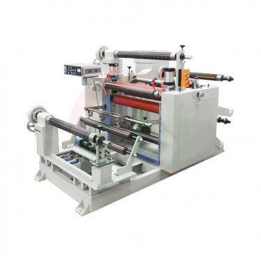
This patent protects the self-cleaning architecture of TOB's calender support equipment. The principle it covers - electromagnet capture plus vacuum pick-up plus screw-driven sweeping, running without a line stop - is how our cleaning units keep electrode calendering stations free of iron chips and dust.
- Automatic electrode dust cleaning and brushing machines
- Electrode roller press / calendering equipment
Related equipment enquiries: request a quote
Frequently Asked Questions
What does patent CN215543717U cover?
It covers a dust and iron removal unit for the rolls of an electrode calender. The unit has a bottom plate structure, side plate structures carrying the upper and lower calender rolls, and a cleaning structure with C-shaped debris attraction boxes fitted with electromagnets, suction ports connected to two air pumps, and screw-driven brush plates that sweep collected debris into a drawer-equipped collection box.
Why is dust and iron removal needed on a calender?
Metal fragments and coating dust collect on the roll faces while the calender runs. If they are not removed they can contaminate the electrode web, and the roller presses in use at the time had to be stopped for cleaning, which heavily cut production efficiency. The unit removes ferrous chips with electromagnets and dust with air pumps while the rolls keep turning.
How do the electromagnets and air pumps remove iron and dust?
An electromagnet at the outer end of each C-shaped debris attraction box is energised during operation and pulls ferrous (iron) chips out of the roll zone. On the opposite side of each roll, suction ports connected by tubes to two air pumps draw dust and loose debris off the roll faces.
How does the unit clear out the debris it captures?
A square brush plate inside each debris box is advanced by a first lead screw and sweeps the magnetically collected chips into a debris collection box with a pull-out drawer; a long brush plate driven by a second lead screw sweeps chips and dust off the bottom plate and out of the machine. All brush motors, pumps and electromagnets are governed by one control panel.
Can the unit be moved between calenders, and how is it fixed in place?
It stands on four threaded levelling posts tipped with suction cups, which fix it firmly in front of a calender, and on a universal caster - a roller wheel on a rotating disc - so it can be wheeled to the next machine. A reinforcing plate between the two side plates stiffens the frame.
Is patent CN215543717U still in force?
Yes. It is Active, filed on 26 August 2021, granted on 18 January 2022, with anticipated expiration on 26 August 2031 under the ten-year Chinese utility model term.
Full specification and drawings: CN215543717U on Google Patents
Explore the full record: all patents by the TOB technical team
 suscribete a nosotros